Codice produttore 9050
MAGNET 0.315"D X 0.098"THICK CYL
Radial Magnets, Inc.
License: See Original Project Raspberry Pi MCU STEMMA
Guide by Liz Clark
Build the path of least resistance with this super smooth rotary encoder. This project uses an AS5600 magnetic angle sensor with a QT Py RP2040 running CircuitPython code to measure the change in magnetic field from a magnet that is being rotated directly above the sensor. When the magnet is rotated, the QT Py RP2040 sends out USB HID commands to raise or lower the volume on a connected device.
The secret sauce for the project is a print in place bearing. This piece attaches to the encoder knob and seats the magnet. This allows you to turn the magnet directly over the AS5600 when you rotate the knob.
You'll need a diametrically polarized magnet for this project, like this one on DigiKey. This means that the magnet is polarized across the diameter. This allows the AS5600 to sense the rotating magnetic field above it.
1 x 8 mm M3 screw
4 x 25 mm M3 screws
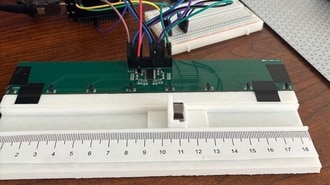
Plug the AS5600 breakout into the STEMMA QT port on the QT Py RP2040 with a STEMMA QT cable.
You can 3D print all of the parts for this project. They are designed to be connected together with M3 screws.
The STL files can be downloaded directly below or from Printables.
The star of the enclosure is a print in place bearing. The magnet is seated in the cutout of the center of the bearing. This allows it to rotate over the AS5600 sensor.
All of the parts print well with standard slicer settings. However, the bearing needs some special settings so that it doesn't fuse:
0.12mm layer height
4 top shell layers
4 bottom shell layers
10% infill
CircuitPython is a derivative of MicroPython designed to simplify experimentation and education on low-cost microcontrollers. It makes it easier than ever to get prototyping by requiring no upfront desktop software downloads. Simply copy and edit files on the CIRCUITPY drive to iterate.
Follow this step-by-step to quickly get CircuitPython running on your board.
Download the latest version of CircuitPython for this board via circuitpython.org
Click the link above to download the latest CircuitPython UF2 file.
Save it wherever is convenient for you.
To enter the bootloader, hold down the BOOT/BOOTSEL button (highlighted in red above), and while continuing to hold it (don't let go!), press and release the reset button (highlighted in red or blue above). Continue to hold the BOOT/BOOTSEL button until the RPI-RP2 drive appears!
If the drive does not appear, release all the buttons, and then repeat the process above.
You can also start with your board unplugged from USB, press and hold the BOOTSEL button (highlighted in red above), continue to hold it while plugging it into USB, and wait for the drive to appear before releasing the button.
A lot of people end up using charge-only USB cables and it is very frustrating! Make sure you have a USB cable you know is good for data sync.
You will see a new disk drive appear called RPI-RP2.
Drag the adafruit_circuitpython_etc.uf2 file to RPI-RP2.
The RPI-RP2 drive will disappear, and a new disk drive called CIRCUITPY will appear.
That's it, you're done! :)
You want to edit your code.py or modify the files on your CIRCUITPY drive but find that you can't. Perhaps your board has gotten into a state where CIRCUITPY is read-only. You may have turned off the CIRCUITPY drive altogether. Whatever the reason, safe mode can help.
Safe mode in CircuitPython does not run any user code on startup and disables auto-reload. This means a few things. First, safe mode bypasses any code in boot.py (where you can set CIRCUITPY read-only or turn it off completely). Second, it does not run the code in code.py. And finally, it does not automatically soft-reload when data is written to the CIRCUITPY drive.
Therefore, whatever you may have done to put your board in a non-interactive state, safe mode gives you the opportunity to correct it without losing all of the data on the CIRCUITPY drive.
To enter safe mode when using CircuitPython, plug in your board or hit reset (highlighted in red above). Immediately after the board starts up or resets, it waits 1000ms. On some boards, the onboard status LED (highlighted in green above) will blink yellow during that time. If you press reset during that 1000ms, the board will start up in safe mode. It can be difficult to react to the yellow LED, so you may want to think of it simply as a slow double click of the reset button. (Remember, a fast double click of reset enters the bootloader.)
If you successfully enter safe mode on CircuitPython, the LED will intermittently blink yellow three times.
If you connect to the serial console, you'll find the following message.
Auto-reload is off.
Running in safe mode! Not running saved code.

CircuitPython is in safe mode because you pressed the reset button during boot. Press again to exit safe mode.

Press any key to enter the REPL. Use CTRL-D to reload.
You can now edit the contents of the CIRCUITPY drive. Remember, your code will not run until you press the reset button, or unplug and plug in your board, to get out of safe mode.
If your board ever gets into a really weird state and CIRCUITPY doesn't show up as a disk drive after installing CircuitPython, try loading this 'nuke' UF2 to RPI-RP2. which will do a 'deep clean' on your Flash Memory. You will lose all the files on the board, but at least you'll be able to revive it! After loading this UF2, follow the steps above to re-install CircuitPython.
Download flash erasing "nuke" UF2
Once you've finished setting up your QT Py RP2040 with CircuitPython, you can access the code and necessary libraries by downloading the Project Bundle.
To do this, click on the Download Project Bundle button in the window below. It will download to your computer as a zipped folder.
# SPDX-FileCopyrightText: Copyright (c) 2025 Liz Clark for Adafruit Industries
#
# SPDX-License-Identifier: MIT
"""AS5600 Encoder"""
import usb_hid
import board
from adafruit_hid.consumer_control import ConsumerControl
from adafruit_hid.consumer_control_code import ConsumerControlCode
import adafruit_as5600

i2c = board.STEMMA_I2C()
sensor = adafruit_as5600.AS5600(i2c)
enc_inc = ConsumerControlCode.VOLUME_INCREMENT
enc_dec = ConsumerControlCode.VOLUME_DECREMENT
cc = ConsumerControl(usb_hid.devices)

last_val = sensor.angle

THRESHOLD = sensor.max_angle // 2 # default max_angle is 4095
# you can change the max_angle. ex: sensor.max_angle = 1000

MIN_CHANGE = 25  # minimum change to register as movement
# increase to make less sensitive, decrease to make more sensitive

while True:
    enc_val = sensor.angle
    if abs(enc_val - last_val) >= MIN_CHANGE or abs(enc_val - last_val) > THRESHOLD:
        # Calculate the difference
        diff = enc_val - last_val
        # Check for wraparound
        if diff > THRESHOLD:
            # Wrapped from ~4095 to ~0 (actually turning backwards)
            cc.send(enc_dec)
        elif diff < -THRESHOLD:
            # Wrapped from ~0 to ~4095 (actually turning forwards)
            cc.send(enc_inc)
        elif diff > 0:
            # Normal forward rotation
            cc.send(enc_inc)
        else:
            # Normal backward rotation (diff < 0)
            cc.send(enc_dec)
        last_val = enc_val
After downloading the Project Bundle, plug your QT Py RP2040 into the computer's USB port with a known good USB data+power cable. You should see a new flash drive appear in the computer's File Explorer or Finder (depending on your operating system) called CIRCUITPY. Unzip the folder and copy the following items to the QT Py RP2040's CIRCUITPY drive.
lib folder
code.py
Your QT Py RP2040 CIRCUITPY drive should look like this after copying the lib folder and code.py file:
At the top of the code, the AS5600 is instantiated over I2C. enc_inc and enc_dec are setup to send the Consumer Control message for volume increase and volume decrease. cc is setup as a Consumer Control USB HID device.
i2c = board.STEMMA_I2C()
sensor = adafruit_as5600.AS5600(i2c)
enc_inc = ConsumerControlCode.VOLUME_INCREMENT
enc_dec = ConsumerControlCode.VOLUME_DECREMENT
cc = ConsumerControl(usb_hid.devices)
A few variables are created before the loop. last_val will hold the last sensor angle reading. THRESHOLD takes the maximum angle of the AS5600 (4095) and divides it by 2 with //. MIN_CHANGE is a user defined value that affects the sensitivity of the encoder. You can increase the value to make the encoder less sensitive or decrease the value to make it more sensitive.
last_val = sensor.angle

THRESHOLD = sensor.max_angle // 2 # default max_angle is 4095
# you can change the max_angle. ex: sensor.max_angle = 1000

MIN_CHANGE = 25  # minimum change to register as movement
# increase to make less sensitive, decrease to make more sensitive
In the loop, the angle is measured with the sensor. If the angle compared to the last measurement is greater than the value of MIN_CHANGE or THRESHOLD, then a volume increase or volume decrease Consumer Control message is sent depending on the direction of the rotation.
The logic used takes wraparound into account, since the measured angle could, for example, jump from 0 to 359 degrees or vice versa when being rotated. The code is setup to pay attention to the direction of the rotation and base the sent Consumer Control message on that value.
while True:
    enc_val = sensor.angle
    if abs(enc_val - last_val) >= MIN_CHANGE or abs(enc_val - last_val) > THRESHOLD:
        # Calculate the difference
        diff = enc_val - last_val
        # Check for wraparound
        if diff > THRESHOLD:
            # Wrapped from ~4095 to ~0 (actually turning backwards)
            cc.send(enc_dec)
        elif diff < -THRESHOLD:
            # Wrapped from ~0 to ~4095 (actually turning forwards)
            cc.send(enc_inc)
        elif diff > 0:
            # Normal forward rotation
            cc.send(enc_inc)
        else:
            # Normal backward rotation (diff < 0)
            cc.send(enc_dec)
last_val = enc_valAttach the bearing to the knob with an 8 mm long M3 screw.
Insert the diametrically polarized magnet into the center cutout over the screw in the bearing. The magnet will fit snugly into the cutout and stick to the stainless steel M3 screw.
Attach the AS5600 to the sensor mount with four M2.5 screws and nuts. The front AS5600 text label on the board silk should be facing away from the two mounting hole standoffs that are slightly taller.
Insert the QT Py RP2040 into the QT Py mount.
Connect the AS5600 to the QT Py RP2040 with a STEMMA QT cable.
Now you'll stack the components together inside the enclosure with four 25 mm M3 screws securing everything.
Start by threading the M3 screws into the bottom enclosure. Insert the QT Py holder with the mounting holes aligned with the USB port facing towards the cut out in the enclosure.
Insert the sensor mount by aligning the screw holes with the enclosure and QT Py mounting holes. There is a longer set of stand-offs on the mount. Those should be opposite of the USB cutout so that the AS5600 silkscreen text is facing towards the USB cutout.
Continue to thread the M3 screws into the sensor mount standoffs.
Line up the bearing mounting holes with the sensor mounting holes. Continue to thread the M3 screws.
Once the M3 screws are fully threaded into the enclosure, the assembly is complete!
If you are concerned about screws on your desk surface, you can add some bumpers to the bottom of the case.
Plug the encoder assembly into a known good data USB C cable. Plug the other end of the cable into a computer or tablet. When you turn the encoder, you'll be able to adjust the volume on the device.
The code is meant as a simple example. You could change it to send different HID inputs, maybe for a video game, or change out the QT Py RP2040 for an ESP32-S2 or S3 to try sending commands over Bluetooth instead of USB. If you do build on this, consider documenting it as an Adafruit Playground note!