Mfr Part # 15168
QWIIC JOYSTICK BOARD
SparkFun Electronics
Single Board Computers Joystick Power Supplies Arduino Qwiic Raspberry Pi SBC
Guide by santaimpersonator
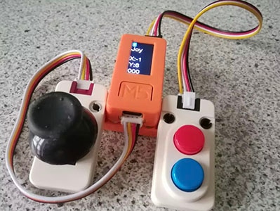
Now, you can easily add an HID/controller to your project! The SparkFun Qwiic Joystick combines the convenience of the Qwiic connection system and an analog joystick that feels reminiscent of the thumbstick from a PlayStation 2 controller.
Thanks to an ATtiny85 on the Qwiic Joystick, all the necessary bits are taken care of and your microcontroller only needs to look for your inputs in the registers of the I2C device.
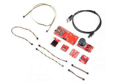
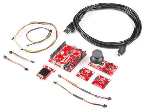
The Qwiic Joystick does need a few additional items for you to get started. The RedBoard Qwiic is for the Arduino examples and the Qwiic Hat is for the Raspberry Pi example (see note below). You may already have a few of these items, so feel free to modify your cart based on your needs.
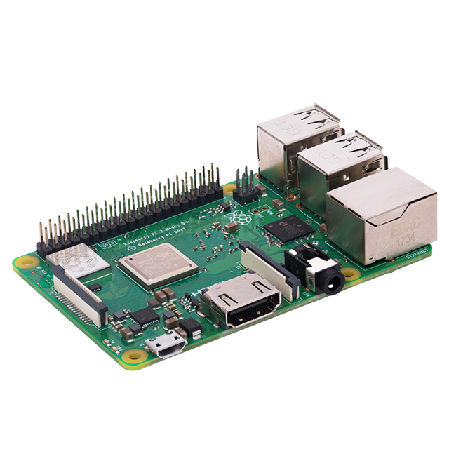
Raspberry Pi Example: If you don't already have them, you will need a Raspberry Pi and standard peripherals. An example setup is listed below.
If you're unfamiliar with jumper pads, I2C, or Python be sure to checkout some of these foundational tutorials.

The Qwiic Joystick utilizes the Qwiic connect system. We recommend familiarizing yourself with the Logic Levels and I2C tutorials (above) before using it. Click on the banner above to learn more about our Qwiic products.
The Qwiic Joystick will report the thumbstick position over I2C and is designed to be compatible with the Qwiic system so you can add it to your project solder-free!
There is a power status LED to help make sure that your Qwiic Joystick is getting power. You can power the board either through the polarized Qwiic connector system or the breakout pins (PWR and GND) provided. The Qwiic system is meant to run on 3.3V, be sure that you are NOT using another voltage when using the Qwiic system.

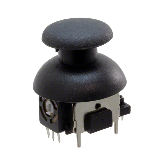
The joystick is similar to the analog joysticks on PS2 (PlayStation 2) controllers. Directional movements are simply measured with two 10 kΩ potentiometers, one for each axis. This joystick also has a select button that is actuated when the joystick is pressed down.
The two potentiometers are connected to the analog to digital converter (ADC) of the ATtiny85. The select button operates as a digital input on the ATtiny85. This allows the firmware to read the knob position and any button presses.
Troubleshooting Tip: Due to resistor manufacturing tolerances, the joystick may not read exactly half of VCC when at rest. You may want to make a note of the "zero" reading, and store that value into your program if necessary.
The joystick contains two potentiometers, connected with a gimbal mechanism that separates the horizontal and vertical movements (orientation shown below).

The potentiometers are the two blue or black boxes on the sides of the joystick. If you move the joystick while watching the center shaft of each potentiometer, you'll see that each of the potentiometers will pick up movement on only one axis. Clever, isn't it?

The joystick also contains a momentary button which activates when you push down on the cap. The button is the small black box on the side of the joystick. If you push down on the cap, you can see a lever pushing down on the head of the button. The lever works no matter what position the joystick is in. That is pretty cool!

With the pre-installed firmware, the ATtiny85 is acts as an intermediary (microcontroller) for the analog and digital inputs from the joystick. This allows the Qwiic Joystick to report its position over I2C.

Note: To flash your own firmware, at minimum, you will need an programmer for the ATtiny and a pogo pin adapter. Writing and uploading firmware is not easily done, unless you know what you are doing; this is inadvisable for beginners.
In the firmware, the Qwiic Joystick’s I2C address is configurable so you can add a bunch of them to the same bus without collision issues.

Note: In the registers for the joystick position, the MSB contains the first 8 bits of the 10-bit ADC value and the LSB contains the last two bits. As an example, this is how the library converts the two registers back to a 10-bit value.
uint_16t full10bitvalue = ((MSB << 8) | LSB) >> 6;
You could potentially only look at the MSB and get an 8-bit reading (for 256 positions). The firmware was intentionally written this way in the hopes that it would be useful for customers who didn't need the full resolution of the joystick position.
Please be aware, the first time the joystick position registers are read, it will have a maximum value (all 1's in binary). I am not sure if it is something in the firmware or if has something to do with the ATtiny85, but the initial read will be 1023. Once that is read, everything reading after should be accurate (excluding the manufacturing tolerances mentioned above). If you have a fix for this issue, please feel free to comment on this tutorial or create a pull request on the GitHub repository.
The board provides four labeled breakout pins. You can connect these lines to the I2C bus of your microcontroller and power pins (3.3V and GND), if it doesn't have a Qwiic connector.

However, the simplest way to use the Qwiic Joystick is through the Qwiic connect system. The connectors are polarized for the I2C connection and power. (*They are tied to the breakout pins.)

Cutting the I2C jumper will remove the 2.2kΩ resistors from the I2C bus. If you have many devices on your I2C bus you may want to remove these jumpers. Not sure how to cut a jumper? Read here!

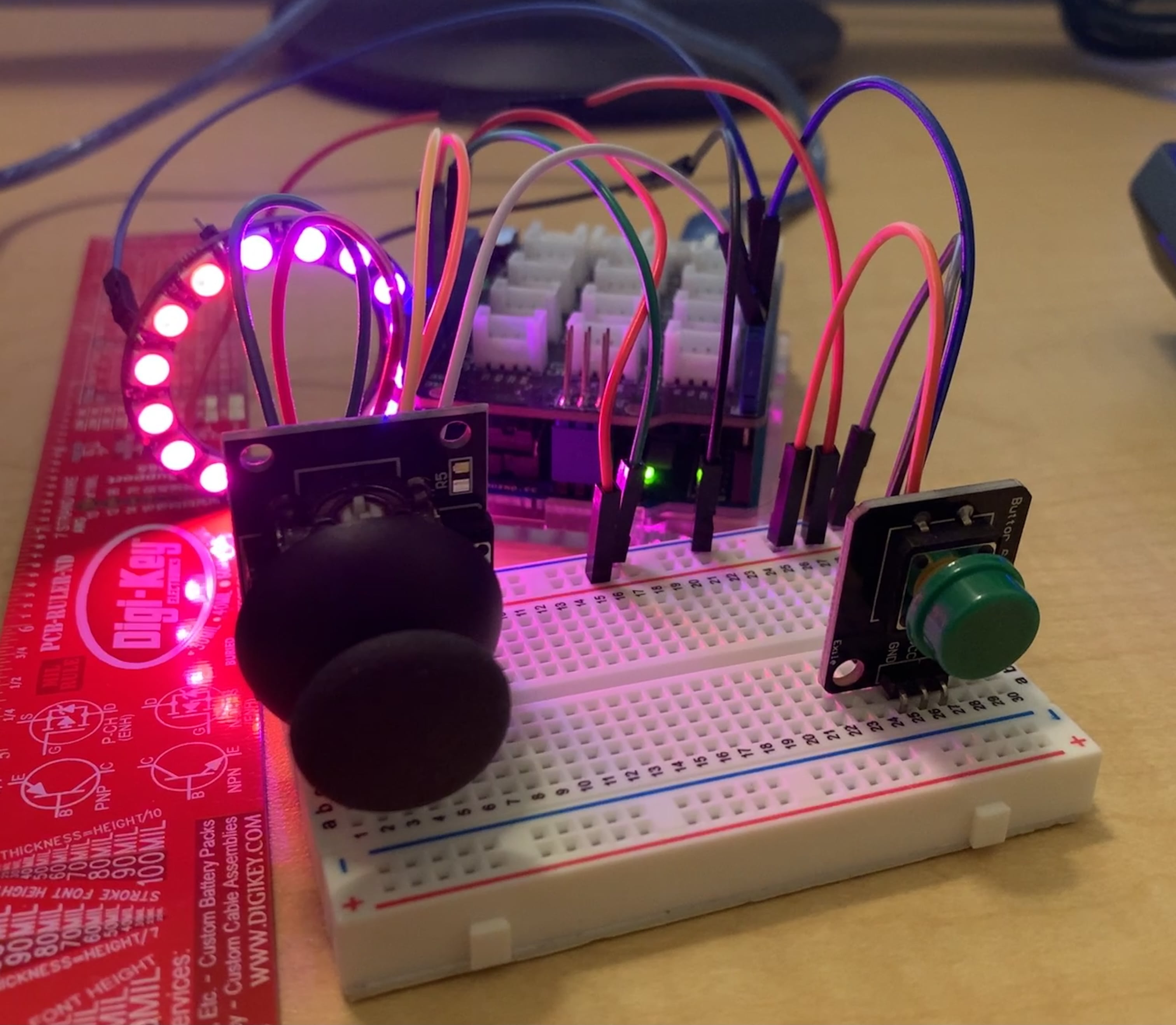
With the Qwiic connector system, assembling the hardware is simple. All you need to do is connect your Qwiic Joystick to the RedBoard Qwiic with a Qwiic cable. Otherwise, you can use the I2C pins of your microcontroller; just be aware of logic levels, that the operating voltage of the ATtiny85 ranges from 1.8 to 5.5V, and the EEPROM needs at least 2V or it will get corrupted.

Note: This tutorial assumes you are familiar with Arduino products and you are using the latest stable version of the Arduino IDE on your desktop. If this is your first time using the Arduino IDE, please review our tutorial on installing the Arduino IDE.
It is best to power the board at the recommended 3.3V of the Qwiic system. However, if you have a board with firmware version 2.3 and happen to accidentally corrupt the EEPROM and inject a new, random I2C address. There is a way to replace the I2C address and store it in the EEPROM again. Follow the following steps exactly, you will need to use the Arduino Library from below:
With the Qwiic connector system, assembling the hardware is simple. You will need a Qwiic cable, a SparkFun Qwiic HAT for Raspberry Pi, and a Raspberry Pi setup with the Raspbian OS, monitor, and standard peripherals. (*If you are unfamiliar with the Qwiic Hat, you can find the Hookup Guide here.)

Note: This tutorial assumes you are familiar with using a Raspberry Pi and you have the latest (full... with recommended software) version of Raspbian OS your Raspberry Pi. You can download the latest version of the Raspbian OS from the Raspberry Pi Foundation website. As of Feb. 13th 2019, we recommend the Raspbian Stretch with desktop and recommended software option.
If this is your first time using a Raspberry Pi, please head over to the Raspberry Pi Foundation website to use their quickstart guides. We have listed a few of them here:
The easiest way to install the Arduino library is by searching SparkFun Qwiic Joystick inside the Arduino library manager. To manually install, head on over to the GitHub Page or feel free to download the library here!
DOWNLOAD: SparkFun Qwiic Joystick Library (ZIP)
The Arduino library is commented and the functions should be self-explanatory. However, below is a detailed list of the available library functions.
.begin() or .begin(Wire, deviceAddress)
Creates a connection to an I2C device over the I2C bus using the default or specified I2C address.
Input: uint8_t deviceAddress
Unasssigned 8-bit integer for device address. If not defined, the library will use the default I2C address stored in the I2C library (0x20).
Output: Boolean
True- Connected to I2C device.
False- No device found or connected.
.isConnected()
Tries to connect to the device at the I2C address stored in the library.
Output: Boolean
True- Connected to I2C device.
False- No device found or connected.
.setI2CAddress(newAddress)
Changes the I2C address to newAddress. Once changed, the new I2C address is saved in the EEPROM of the Qwiic Joystick. Reconnects to device using new I2C address. (The new address is printed out in the Serial Monitor.)
Input: uint8_t newAddress
Unasssigned 8-bit integer for device address.
.getHorizontal()
Returns the ADC value of the joystick horizontal position.
Output: uint16_t
Unasssigned 10-bit integer [0 - 1023] for ADC value of the joystick position in the horizontal axis.
.getVertical()
Returns the ADC value of the joystick vertical position.
Output: uint16_t
Unasssigned 10-bit integer [0 - 1023] for ADC value of the joystick position in the vertical axis.
.getButton()
Returns the current button state (clears check button indicator - see below).
Output: byte
0 - Button is currently being pressed.
1 - Button is currently unpressed.
.checkButton()
Indicates if the button was pressed between reads of the button state or calls of this function. The register for this indicator is then cleared.
Output: byte
0 - Button is was NOT pressed.
1 - Button is was pressed.
.getVersion()
Returns a string of the firmware version number.
Output: String AAA.BBB
AAA - Firmware Version (Major)
BBB - Firmware Version (Minor)
There are four examples in the Qwiic Joystick Arduino Library to get you started with using Qwiic Joystick. These example files are named with self-explanatory titles, but in case you want more information, see the descriptions below.
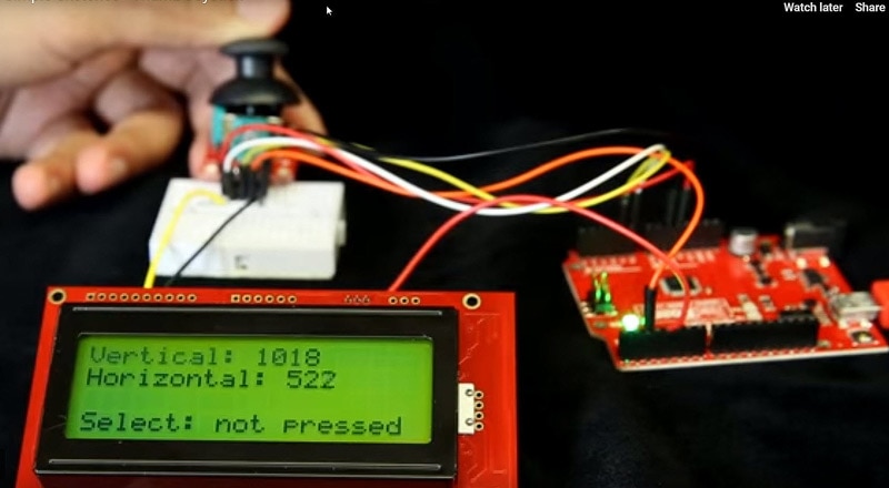
This example connects to the Qwiic Joystick using the default I2C address saved in the library. The sketch looks at the registers for the current joystick position and button state. The example then prints out those values over the Serial Monitor.
This example connects to the Qwiic Joystick using the default I2C address set in the sketch and then prints out the I2C address and firmware version over the Serial Monitor. The sketch then, takes an input from the Serial Monitor to change the I2C address using a decimal value (DEC). Once the I2C address is changed, it is stored in the EEPROM of the Qwiic Joystick. After, the sketch connects to the joystick using the new I2C address and reads the registers for the firmware version again. The example then prints out those values over the Serial Monitor again.
This example is from the I2C scanner example from the Arduino Playground webpage. The sketch scans for devices on the I2C bus and reports them on the Serial Monitor. This is useful for users who have forgotten the changed I2C address of their boards.
This example shows a basic example of how to begin to use the Qwiic Joystick as an HID. The example sketch takes values of the joystick and converts it to directional printouts on the Serial Monitor.
Note: This section is an example of using the Qwiic Joystick and the RedBoard Qwiic with the Arduino IDE. It is not intended to be a guide for using I2C devices with the Arduino IDE.
Please use the following links and the internet for a better understanding of I2C and how it works in the Arduino IDE:
This sketch looks at the registers for the current joystick position and button state; the values are sent to the Serial Monitor. Make sure you are using a baudrate of 9600bps.

This sketch takes an entry from the Serial Monitor, in a decimal value, and changes the I2C address of the device. The firmware version is then read to confirm that the address was changed. Make sure you are using a baudrate of 9600bps.

This sketch is from the I2C scanner example from the Arduino Playground webpage. The sketch scans for devices on the I2C bus and reports them on the Serial Monitor. Make sure you are using a baudrate of 9600bps.
This sketch takes values of the joystick and converts it to directional printouts on the Serial Monitor. It also reads out if the button was pressed. Make sure you are using a baudrate of 9600bps.

Update: We've written a full Python package for the Qwiic Joystick that can be found here:
For installation instructions, please refer to the repository's README file.
Note: This section is an example of using the Qwiic Joystick with the Raspberry Pi in Python. It is not intended to be a guide for using I2C devices with a Raspberry Pi or a tutorial on Python.
Please use the following links and the internet for a better understanding of I2C and how it works in the Arduino IDE:
If it isn't already enabled, enable I2C interface in Preferences > Raspberry Pi Configuration panel.

 Enabling the I2C through the configuration panel.
On the (full) Raspbian OS, i2ctools should be pre-installed (if it is not, follow the instructions here). With the Qwiic Joystick and Qwiick Hat attached to the Raspberry Pi, run the following command in the terminal/commandline.
i2cdetect -y 1
Download the Python Examples from the GitHub repository. All you need to do is open an example python file and execute the module. You can do this in Python 3 or another compatible, programming text editor like Geany.
Below is a screenshot of the python shell from the Basic Readings example file.

When you run the Snake Game example code, you only need to click the button to start the game. (*Shout out to Al Sweigart for his Wormy example, which was adapted to work with the Qwiic Joystick.)

Troubleshooting Tip: I did run into an error with the python example codes. Unfortunately, I am not an expert in Python and the Raspberry Pi. However, I got around this by having the error print out instead of terminating the script. From what I could deduce based on the available information on the internet, the error [Errno 121] Re mote I/O error is an issue with the I2C bus and how SMBUS interacts with the slave device.
You will also get an [Errno 121] Remote I/O error if your I2C address is defined wrong.
For more information, check out the resources below:
Need help getting started with Arduino and I2C? Check out these resources here:
Need help getting started with your Raspberry Pi? Check out these resources here:
Need help getting started with Python and I2C? Check out these resources here: