Settings
 Fast Delivery
 Free Shipping
 Incoterms
 Payment Types


 Marketplace Product

Mfr Part # ST0240
MINI TRAFFIC LIGHT LED MODULE
SunFounder

License: GNU Lesser General Public License LED Strips Microcontrollers PWM Arduino ESP32
In this tutorial, we will learn how to control a traffic light using a membrane keypad and Arduino.
Watch the video.
Learn more about Visuino: What is Visuino
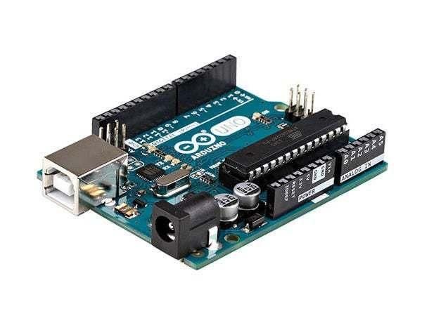
Arduino UNO (or any other Arduino)
Visuino program: Download Visuino
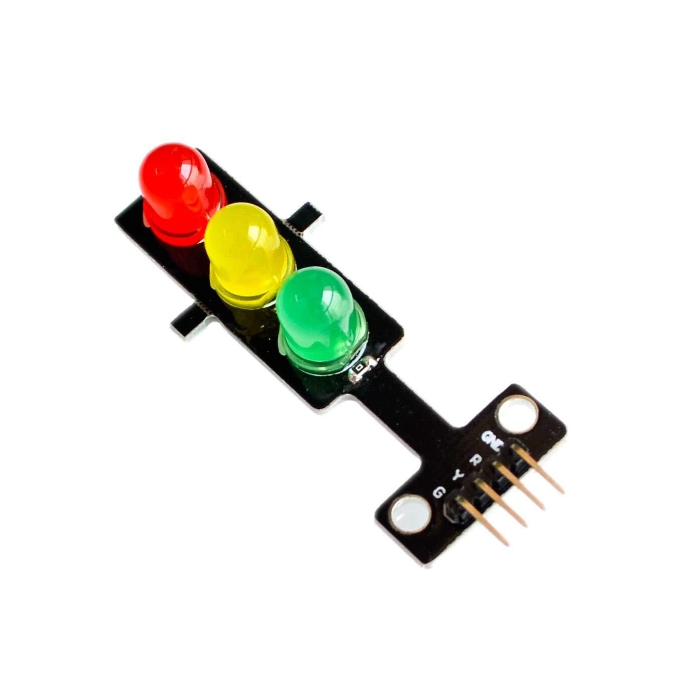
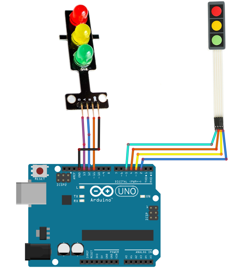
Connect "Traffic lights module" pin [GND] to Arduino pin[GND]
Connect "Traffic lights module" pin [R] to Arduino digital pin[11]
Connect "Traffic lights module" pin [Y] to Arduino digital pin[12]
Connect "Traffic lights module" pin [G] to Arduino digital pin[13]
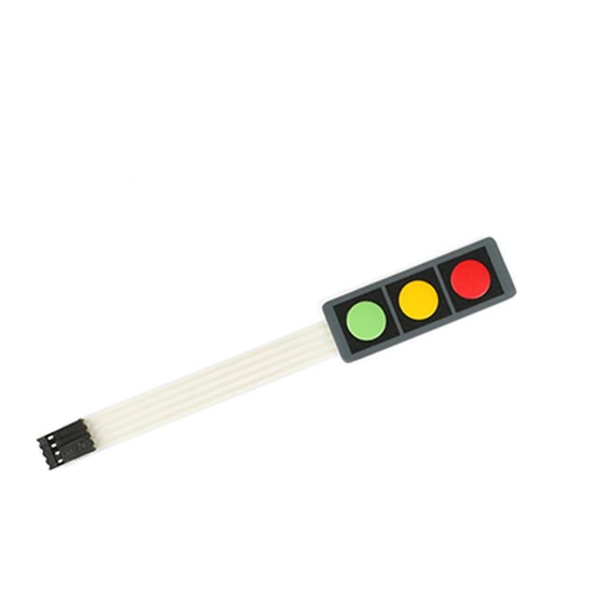
Connect the Membrane Keypad pin [1] to Arduino digital pin[2]
Connect the Membrane Keypad pin [2] to Arduino digital pin[3]
Connect the Membrane Keypad pin [3] to Arduino digital pin[4]
Connect the membrane keypad pin [4] to Arduino digital pin[5]
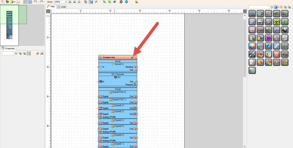
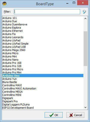
Start Visuino as shown in the first picture. Click on the "Tools" button on the Arduino component (Picture 1) in Visuino. When the dialog appears, select "Arduino UNO" as shown in Picture 2
Add "Keypad" component
Add 3X "Digital Multi Source" component
Add 3X "Toggle(T) Flip-Flop" component
Add "Pulse Generator" component
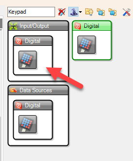
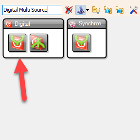
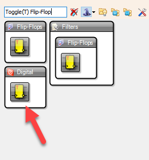
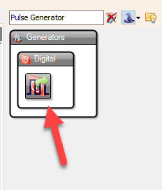
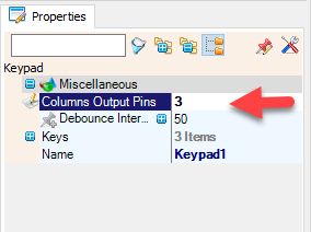
Select "Keypad1" and in the properties window set "Columns Output Pins" to 3
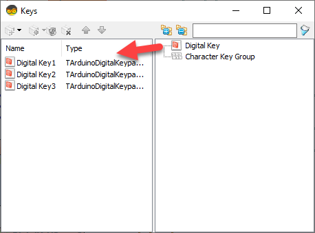
Double click on "Keypad1" and in the "Keys" window, drag 3X "Digital Key" to the left side
Close the window
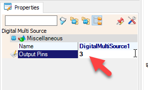
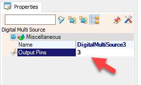
Select "DigitalMultiSource1" and in the properties window set "Output Pins" to 3
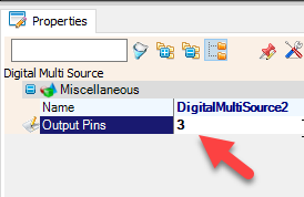
Select "DigitalMultiSource2" and in the properties window set "Output Pins" to 3
Select "DigitalMultiSource3" and in the properties window set "Output Pins" to 3
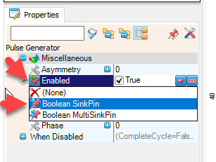
Select "PulseGenerator1" and in the properties window select "Enabled" and click on the Pin icon and select "Boolean SinkPin"
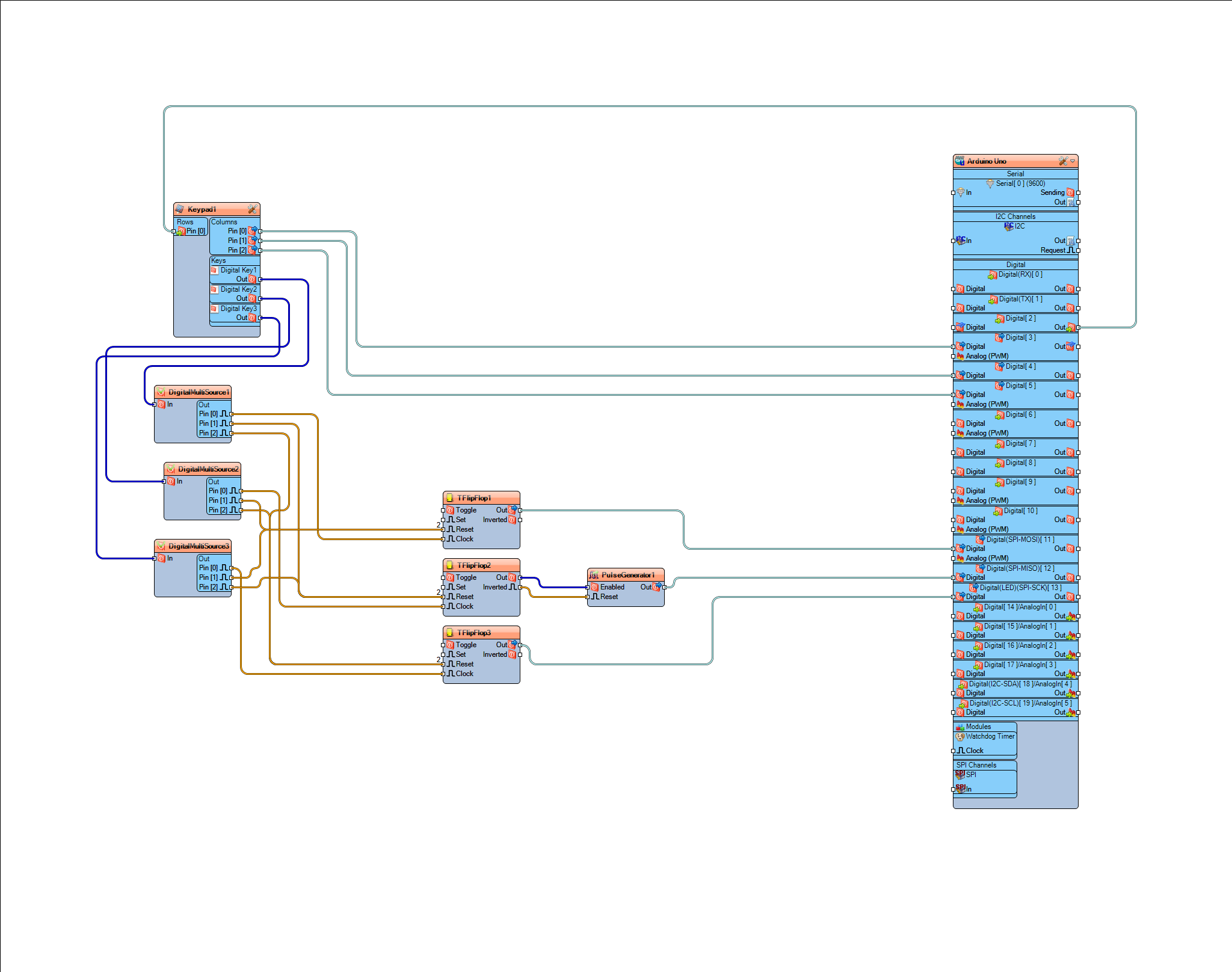
Connect Arduino Digital Pin[2] to "Keypad1" > Rows Pin [0]
Connect "Keypad1" > Columns Pin [0] to Arduino Digital Pin[3]
Connect "Keypad1" > Columns Pin [1] to Arduino Digital Pin[4]
Connect "Keypad1" > Columns Pin [2] to Arduino Digital Pin[5]
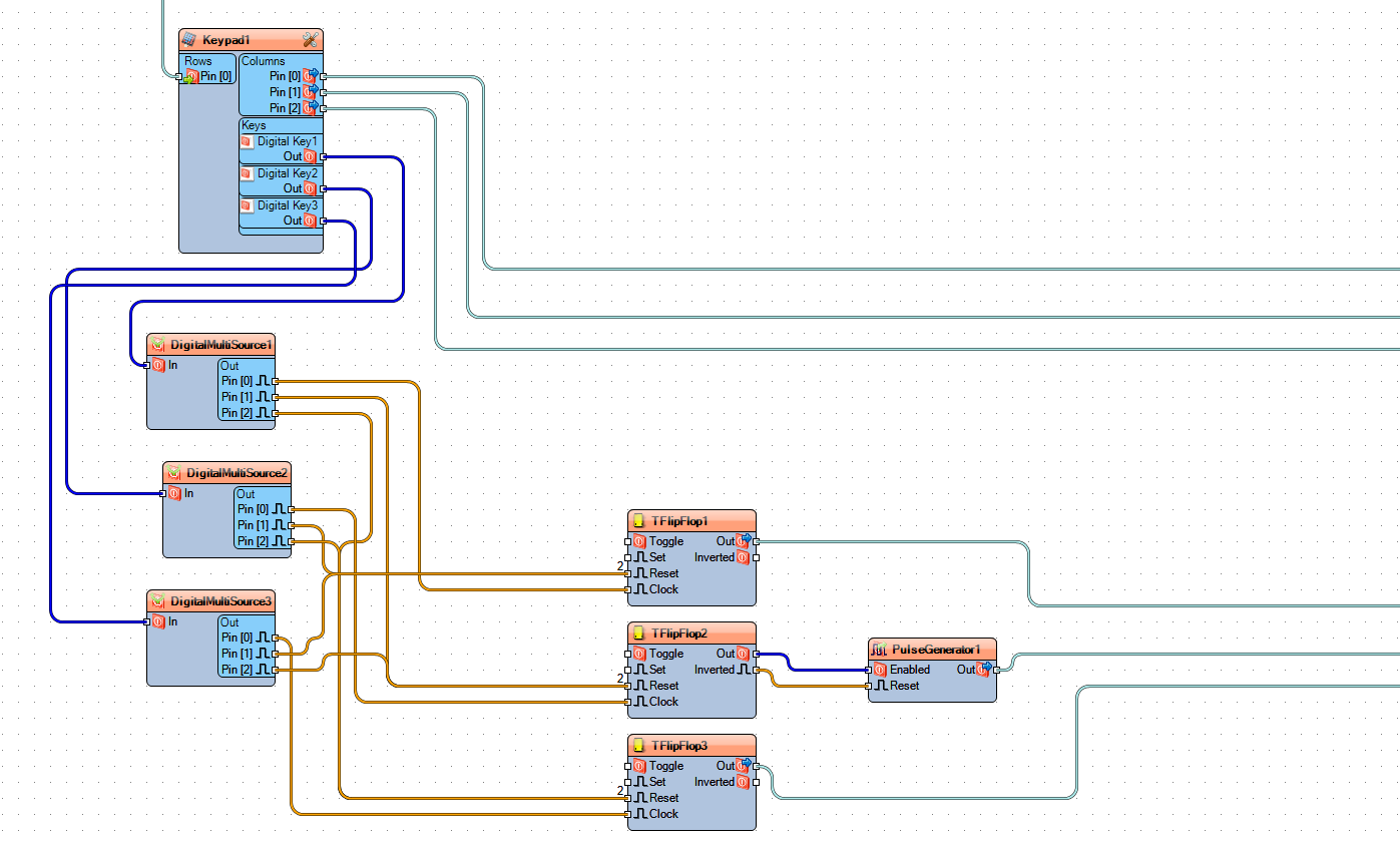
Connect "Keypad1" > Keys > Digital Key1 Pin [Out] to "DigitalMultiSource1" Digital Pin[In]
Connect "Keypad1" > Keys > Digital Key2 Pin [Out] to "DigitalMultiSource2" Digital Pin[In]
Connect "Keypad1" > Keys > Digital Key3 Pin [Out] to "DigitalMultiSource3" Digital Pin[In]
Connect "DigitalMultiSource1" Digital Pin[0] to "TFlipFlop1" pin [Clock]
Connect "DigitalMultiSource1" Digital Pin[1] to "TFlipFlop2" pin [Reset]
Connect "DigitalMultiSource1" Digital Pin[2] to "TFlipFlop3" pin [Reset]
Connect "DigitalMultiSource2" Digital Pin[0] to "TFlipFlop2" pin [Clock]
Connect "DigitalMultiSource2" Digital Pin[1] to "TFlipFlop1" pin [Reset]
Connect "DigitalMultiSource2" Digital Pin[2] to "TFlipFlop3" pin [Reset]
Connect "DigitalMultiSource3" Digital Pin[0] to "TFlipFlop3" pin [Clock]
Connect "DigitalMultiSource3" Digital Pin[1] to "TFlipFlop1" pin [Reset]
Connect "DigitalMultiSource3" Digital Pin[2] to "TFlipFlop2" pin [Reset]
Connect "TFlipFlop1" pin [Out] to Arduino Digital Pin[11]
Connect "TFlipFlop2" pin [Out] to "PulseGenerator1" Pin[Enabled]
Connect "TFlipFlop2" pin [Inverted] to "PulseGenerator1" Pin[Reset]
Connect "PulseGenerator1" Pin[Out] to Arduino Digital Pin[12]
Connect "TFlipFlop3" pin [Out] to Arduino Digital Pin[13]
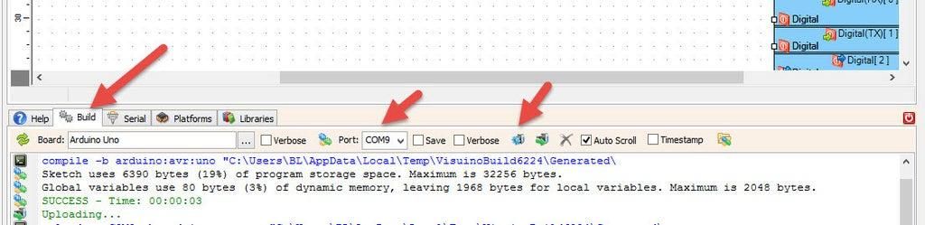
In Visuino, at the bottom, click on the "Build" tab, make sure the correct port is selected, then click on the "Compile/Build and Upload" button.
If you power the Arduino UNO module and press the membrane button, the traffic light module will start to change colors according to the pressed button.
Congratulations! You have completed your project with Visuino. Also attached is the Visuino project that I created for this. You can download it and open it in Visuino: https://www.visuino.eu