Mfr Part # 3333
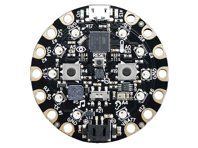
CIRCUIT PLAYGROUND EXPRESS
Adafruit Industries LLC
License: See Original Project 3D Printing Microcontrollers Keyboards Keypad Switches Circuit Playground
Guide by Ruiz Brothers
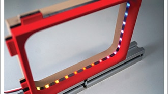
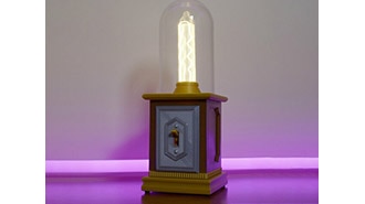
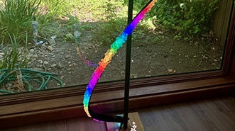
Build a 3D printed desktop sized lamp using Circuit Playground Express. Use a mini-IR remote to control the brightness and change the colors of the LEDs. It features five multi-colored panels that have geometric designs.
A shoji lantern (or Andon) is a traditional Japanese light fixture featuring translucent paper panels usually set within a wooden frame. It adds a gentle warm glow to bedrooms and ideal for creating a calm meditative atmosphere. Originally designed to protect an oil wick flame from the wind, this project modernizes the concept with LEDs.
This uses a sliding dovetail joint for the frame which is a woodworking technique. It provides a strong, self-locking connection by sliding a tail into a corresponding socket. The tail features a trapezoidal shape. It's good for mechanical strength and resistant to being pulled apart.
To stay within the traditional woodworking technique, this doesn't use any hardware fasteners to assemble. No screws or glue, just snap fit 3D printed parts!
A mini-IR remote can be used to change the color of the ten NeoPixel LEDs. 0-9 numbers are assigned to change the colors while the play/pause button turns them all off. The up and down arrows are used to increase or decrease the brightness of the LEDs.
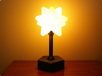
The panels are 3D printed using a translucent filament. They utilize a multi-material add-on that uses four different colored filaments combined in a single printed part.
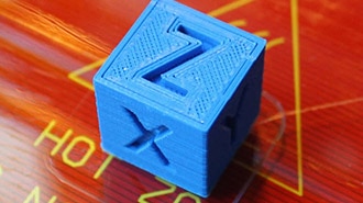
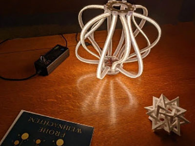
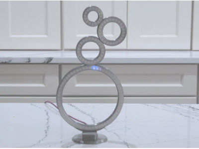
The shapes are inspired by impossible objects that use optical illusions to appear like three-dimensional geometric shapes.
Panels slide into the stiles (vertical uprights) and are secured within the frame. The frame can hold up to five different panels. The panels can be swapped out for different designs making this a modular assembly.
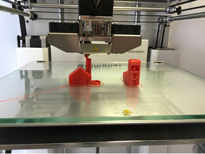
Individual 3MF files for 3D printing are oriented and ready to print on FDM machines using PLA filament. Original design source files may be downloaded using the links below.
A set of four rails are fitted onto the four stiles with the dovetails sliding into corresponding grooves.
The bottom panel snap fits onto the lower rails.
A set of four panels slide in between the stiles.
Another set of rails are fitted over the panels and slide in between the stiles.
The CircuitPlayground PCB snap fits onto the bottom cover.
The top panel is fitted into the recess on the top cover.
The top cover locks onto the upper set of rails.
The frame requires multiple copies of the stiles and rails. Use the 3MF file Stile and Rails Set.3mf to print a full set of parts needed to build the frame. Otherwise, you can print each part individually.
7x rails
1x cable rail
4x stiles
The parts require a 3D printer with a minimum build volume of 124 (X) x 124 (Y) x 136mm (Z).
This guide assumes an AMS multi-color capable 3D printer is being used. The panels are in the 3MF file format, which includes bodies, colors and slicing meta data. You can choose any four colors of filaments you'd like and have the option to change the colors for each body. List of filaments used are linked below.
As we continue to develop CircuitPython and create new releases, we will stop supporting older releases. If you are running an older version of CircuitPython, you need to update. Click the button below to download the latest!
Follow this quick step-by-step for super-fast Python power :)
Download the latest version of CircuitPython for this board via CircuitPython.org
Click the link above and download the latest UF2 file.
Download and save it to your Desktop (or wherever is handy).
Plug your Circuit Playground Express into your computer using a known-good USB cable.
A lot of people end up using charge-only USB cables and it is very frustrating! So make sure you have a USB cable you know is good for data sync.
Double-click the small Reset button in the middle of the CPX, you will see all of the LEDs turn green. If they turn all red, check the USB cable, try another USB port, etc.
(If double-clicking doesn't do it, try a single-click!)
You will see a new disk drive appear called CPLAYBOOT.
Drag the adafruit-circuitpython-etc...uf2 file onto it.
The CPLAYBOOT drive will disappear, and a new disk drive will appear called CIRCUITPY.
That's it! You're done :)
For more detailed info on installing CircuitPython, check out Installing CircuitPython.
Once you've finished setting up your Circuit Playground Express with CircuitPython, you can access the code and necessary libraries by downloading the Project Bundle.
To do this, click on the Download Project Bundle button in the window below. It will download to your computer as a zipped folder.
# SPDX-FileCopyrightText: 2018 Kattni Rembor for Adafruit Industries
#
# SPDX-License-Identifier: MIT

import adafruit_irremote
import board
import neopixel
import pulseio

pixels = neopixel.NeoPixel(board.NEOPIXEL, 10)

pulsein = pulseio.PulseIn(board.REMOTEIN, maxlen=120, idle_state=True)
decoder = adafruit_irremote.GenericDecode()

last_command = None

brightness_up = 95  # Up arrow
brightness_down = 79  # Down arrow

command_to_color = {  # button = color
    247: (255, 0, 0),  # 1 = red
    119: (255, 40, 0),  # 2 = orange
    183: (255, 150, 0),  # 3 = yellow
    215: (0, 255, 0),  # 4 = green
    87: (0, 255, 120),  # 5 = teal
    151: (0, 255, 255),  # 6 = cyan
    231: (0, 0, 255),  # 7 = blue
    103: (180, 0, 255),  # 8 = purple
    167: (255, 0, 20),  # 9 = magenta
    207: (255, 255, 255),  # 0 = white
    127: (0, 0, 0),  # Play/Pause = off
}

while True:
    pulses = decoder.read_pulses(pulsein, max_pulse=5000)
    command = None
    try:
        code = decoder.decode_bits(pulses)
        if len(code) > 3:
            command = code[2]
        print("Decoded:", command)
        print("-------------")
    except adafruit_irremote.IRNECRepeatException:  # Catches the repeat signal
        command = last_command
    except adafruit_irremote.IRDecodeException:  # Failed to decode
        pass

    if not command:
        continue
    last_command = command

    if command == brightness_up:
        pixels.brightness += 0.1
    elif command == brightness_down:
        pixels.brightness -= 0.1
    elif command in command_to_color:
        pixels.fill(command_to_color[command])
After downloading the Project Bundle, plug your Circuit Playground Express into the computer's USB port with a known good USB data+power cable. You should see a new flash drive appear in the computer's File Explorer or Finder (depending on your operating system) called CIRCUITPY. Unzip the folder and copy the following items to the Feather Prop Maker's CIRCUITPY drive.
lib folder
code.py
Your Circuit Playground Express CIRCUITPY drive should look like this after copying the lib folder and code.py file:
At the top of the code, we import the four libraries we'll be using in our code. Then we setup use of those libraries. First, we assign last_command for use later. Then, we assign brightness_up to the IR command code associated with the up arrow on the IR remote, and brightness_down to the code for the down arrow.
import adafruit_irremote
import board
import neopixel
import pulseio

pixels = neopixel.NeoPixel(board.NEOPIXEL, 10)

pulsein = pulseio.PulseIn(board.REMOTEIN, maxlen=120, idle_state=True)
decoder = adafruit_irremote.GenericDecode()

last_command = None
brightness_up = 95  # Up arrow
brightness_down = 79  # Down arrow
The keys are the IR codes for the eleven buttons we're using, and the values are their associated (r, g, b) tuples. NeoPixel colors are represented using red, green and blue in values of 0 - 255 to determine the amount of a given color. We've used comments on each line to identify which button on the remote and assigned color the dictionary is referring to.
command_to_color = {  # button = color
    247: (255, 0, 0),  # 1 = red
    119: (255, 40, 0),  # 2 = orange
    183: (255, 150, 0),  # 3 = yellow
    215: (0, 255, 0),  # 4 = green
    87: (0, 255, 120),  # 5 = teal
    151: (0, 255, 255),  # 6 = cyan
    231: (0, 0, 255),  # 7 = blue
    103: (180, 0, 255),  # 8 = purple
    167: (255, 0, 20),  # 9 = magenta
    207: (255, 255, 255),  # 0 = white
    127: (0, 0, 0),  # Play/Pause = off
}
The first two sections of code inside the loop are designed to read the incoming IR signals, decode them, and prepare them for practical use.
To simplify the amount of IR noise, the line if len(code) > 3: says the signal must be longer longer than three values before we do anything with it. The decoded signal from each button on this remote is four numbers in a list format: [0, 0, 0, 0]. You need only the third number from that list. When we get a code of the correct length, we assign command to be the third value from the list by assigning command = code[2].
The two print statements are here to identify the command code for the unused buttons on the remote. Some remotes will have different command. Reference the commands in the REPL output to update and change the values in the commands dictionary.
while True:
    pulses = decoder.read_pulses(pulsein, max_pulse=5000)
    command = None
    try:
        code = decoder.decode_bits(pulses)
        if len(code) > 3:
            command = code[2]
        print("Decoded:", command)
        print("-------------")
    except adafruit_irremote.IRNECRepeatException:  # Catches the repeat signal
        command = last_command
    except adafruit_irremote.IRDecodeException:  # Failed to decode
        pass

    if not command:
        continue
    last_command = command

    if command == brightness_up:
        pixels.brightness += 0.1
    elif command == brightness_down:
        pixels.brightness -= 0.1
    elif command in command_to_color:
pixels.fill(command_to_color[command])Start by getting the four stiles and rails together. Make sure there are three rails and one cable rail is in the set.
Arrange them in the correct orientation with the four stiles on each corner with a rail in between them.
Note, the nubs are facing inside the frame with the center channel facing up.
Begin joining the rails to the stiles, starting with adding one rail to a single stile.
Slide a rail into a stile, with the dovetail fitted into the mating grove. Push the rail all the way down until it reaches the end of the groove.
Repeat the assembly for the remaining stiles and rails.
Take a moment to inspect the frame, making sure the nubs are facing inwards and the channels are facing up.
Orient the bottom panel so the side with the doubled tabs (two shorter tabs) are aligned with the rail cable part of the frame.
Fit the bottom panel in between the four stiles. Firmly press the bottom panel into the rails so the tabs snap fit onto the nubs.
Take a moment to inspect the framed assembly, making sure the rails are oriented correctly with the center channels in the rails facing up, and the cable rail matched with the double tabbed side of the bottom panel.
Orient the Circuit Playground PCB so the micro-USB port is facing the rail with the matching cutout.
Fit one side of the PCB under the clips on the bottom panel. Then, slightly flex the panel to allow the other side of the PCB to fit under the remaining tab.
Press down on the PCB until it is fully seated onto the four standoffs on the bottom panel.
Get the four panels ready to install onto the four stiles of the frame.
Slide the panels in between the stiles, with the edges fitting into the grooves.
Repeat the installation for all four panels, making sure each panel is oriented correctly.
Get the remaining four rails ready to install onto the frame.
Orient the four rails so the nubs are facing outside the frame.
Carefully fit the rails onto the stiles with the dovetails fitted in the corresponding grooves.
Make sure the panels are being captured into the center channels of the rails and the nubs on the rails are facing outwards.
Get the top panel and top cover ready.
Place the top panel into the recess on the top cover.
Insert the micro-USB cable through the cutout on the rail, then firmly push the plug into the connector on the Circuit Playground Express PCB.
Run a quick power test to ensure the USB cable is fully seated.
With the top cover laying flat on the surface (snap fit tabs facing up) begin placing the lamp framing onto the tabs.
Firmly press the frame onto the top cover so the tabs lock onto the nubs.
Check each side of the framing, making sure the tabs are fully capturing the nubs on the rails.
Flip the assembled frame upright and power the Circuit Playground Express with the 5V USB power supply.
Use the IR mini remote to turn on the NeoPixel LEDs.
Use the buttons on the remote to change the colors of the LEDs. Use the up and down arrows to increase/decrease the brightness of the LEDs.
1 = Red color
2 = Orange color
3 = Yellow color
4 = Green color
5 = Teal color
6 = Cyan color
7 = Blue color
8 = Purple color
9 = Magenta color
0 = White color
Play/Pause = All LEDs off