DC Motor Smooth Start, Speed and Direction Using a Potentiometer, OLED
2026-04-27 | By Ron Cutts
License: GNU Lesser General Public License LED Strips Microcontrollers Motors Arduino ESP32
In this tutorial, we will learn how to use an L298N DC MOTOR CONTROL driver and a potentiometer to control a DC motor smooth start, speed, and direction with two buttons and display the potentiometer value on the OLED display.
Watch a demonstration video.
What You Will Need
Two push buttons
Visuino program: Download Visuino


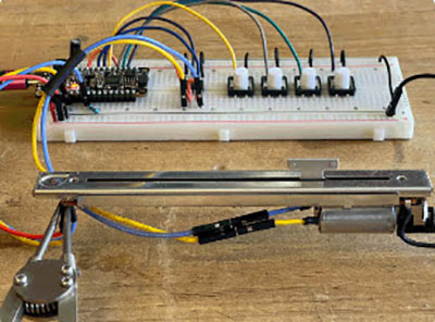
The Circuit
Connect button1 second pin to Arduino digital pin 6
Connect button1 second pin to resistor1
Connect button2 first pin to breadboard positive pin (red line)
Connect button2 second pin to Arduino digital pin 7
Connect button2 second pin to resistor2
Connect resistor1 to the breadboard negative pin (blue line)
Connect resistor2 to the breadboard negative pin (blue line)
Connect digital pin(2) from Arduino to motor driver pin (IN2)
Connect digital pin(3) from Arduino to motor driver pin (IN1)
Connect the DC motor to one side of the motor driver
Connect the power supply (batteries) pin (gnd) to the motor driver controller pin (gnd)
Connect the power supply (batteries) pin (+) to motor driver controller pin (+)
Connect GND from the Arduino to the motor driver controller pin (gnd)
Connect the potentiometer pin (DTB) to the Arduino Analog pin (A0)
Connect the potentiometer pin (VCC) to the Arduino pin (5V)
Connect the potentiometer pin (GND) to the Arduino pin (GND)
Connect OLED Display pin (GND) to Arduino pin (GND)
Connect OLED Display pin (VCC) to Arduino pin (5V)
Connect OLED Display pin (SCL) to Arduino pin (SCL)
Connect OLED Display pin (SDA) to Arduino pin (SDA)

Start Visuino, and Select the Arduino UNO Board Type
To start programming the Arduino, you will need to have the Arduino IDE installed from here: http://www.arduino.cc/.
Please be aware that there are some critical bugs in Arduino IDE 1.6.6. Make sure that you install 1.6.7 or higher; otherwise, this will not work! If you have not done so, follow the steps to set up the Arduino IDE to program the ESP8266! The Visuino: https://www.visuino.eu also needs to be installed. Start Visuino as shown in the first picture. Click on the "Tools" button on the Arduino component (Picture 1) in Visuino. When the dialog appears, select "Arduino UNO" as shown in Picture 2


In Visuino, add AND Connect Components
Add "Dual DC Motor Driver Digital and PWM Pins Bridge (L9110S, L298N)" component
Add "Speed and Direction To Speed" component
In the "Properties window " set "Initial Reverse" to "True"Add "SR Flip-Flop" component. Connect the Arduino Board digital pin[6] to "SRFlipFlop1" pin[Set]
Add "SSD1306/SH1106 OLED Display (I2C)" component.
Double-click on the "DisplayOLED1" and in the elements window, drag "Text Field" to the left and in the properties window, set size:3, Y:30Add "Ramp To Analog Value" component
Connect Arduino Board digital pin[7] to "SRFlipFlop1" pin[Reset]
Connect Arduino board's AnalogIn pin[0] to "RampToValue1" pin[In]
Connect Arduino Board AnalogIn pin[0] to "DisplayOLED1">Text Field1 pin[In]
Connect "RampToValue1" pin[Out] to SpeedAndDirectionToSpeed1 pin[Speed]
Connect "DisplayOLED1" pin Out[I2C] to Arduino board pin I2C
Connect "SRFlipFlop1" pin[Out] to "SpeedAndDirectionToSpeed1" pin[Reverse]
Connect "SpeedAndDirectionToSpeed1" pin[Out] to "DualMotorDriver1" > Motors[0] pin [In]
Connect "DualMotorDriver1" > Motors[0] pin [Direction(B] to Arduino board digital pin[2]
Connect "DualMotorDriver1" > Motors[0] pin [Speed(A)] to Arduino board digital pin[3]


In Visuino, Press F9 or click on the button shown in Picture 1 to generate the Arduino code, and open the Arduino IDE
In the Arduino IDE, click on the Upload button to compile and upload the code (Picture 2)
")
 photo 2")
Play
If you power the Arduino Uno module and add batteries for the motor controller, the DC motor is ready to spin.
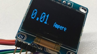
By sliding the potentiometer, you can regulate the motor speed and change the direction by pushing the buttons. The potentiometer value will be displayed on the OLED display, and because of the "Ramps" component, the motor will change its speed more smoothly. Congratulations! You have completed your project. Also attached is the Visuino project that I created for this. You can download it here and open it in Visuino: https://www.visuino.eu