Build a Wireless Sensor Network Using NRF24L01 & Arduino
2026-05-08 | By Ron Cutts
License: GNU Lesser General Public License Bluetooth / BLE Temperature Wifi Arduino ESP32
Here, we are going to explore how to build a Wireless Sensor Network
Using NRF24L01 & Arduino, in this example, we are going to use one NRF24L01 as a receiver and two NRF24L01 modules as a sender for the Temperature & Humidity using a DHT sensor.
The key point of this tutorial is to learn how to add an ID to each of the modules so that the receiver can know which module is sending the data.
Also check out this amazing tutorial made by Boian Mitov, Arduino and Visuino: Long Distance Remote Light Sensor With RFM95W/RFM98W LoRa Shields
Learn more about Visuino: What is Visuino
What You Will Need
3X Arduino UNO (or any other Arduino)
Visuino program: Download Visuino


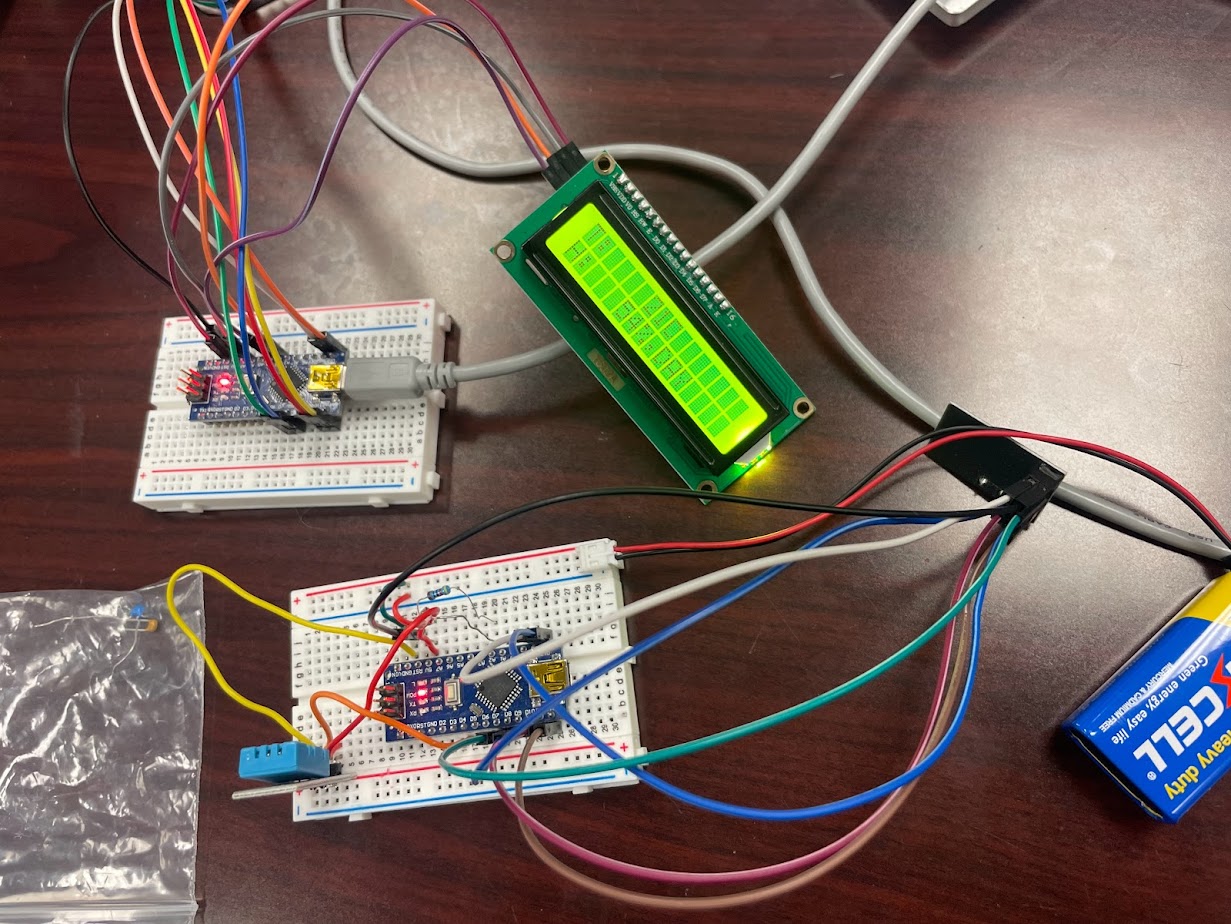
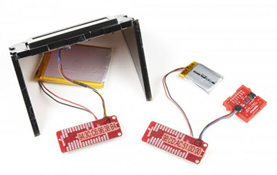
The Circuit
For this project, we are using an NRF24L01 module together with a voltage adapter.
Wiring the Sender 1 Arduino:
Connect the NRF24L01 Adapter pin [VCC] to the Arduino pin [5V]
Connect the NRF24L01 Adapter pin [GND] to the Arduino pin [GND]
Connect the NRF24L01 Adapter pin "Chip Enable" [CE] to the Arduino Digital pin [9]
Connect the NRF24L01 Adapter pin "Chip Select" [CSN] to the Arduino Digital pin [10]
Connect the NRF24L01 Adapter pin [SCK] to the Arduino Digital pin [13]
Connect the NRF24L01 Adapter pin [MO] to the Arduino Digital pin [11]
Connect the NRF24L01 Adapter pin [MI] to the Arduino Digital pin [12]
Connect DHT11 sensor pin [VCC] to Arduino pin [5V]
Connect DHT11 sensor pin [GND] to Arduino pin [GND]
Connect DHT11 sensor pin [OUT] to Arduino Digital pin [2]
Wiring the Sender 2 Arduino:
Connect the NRF24L01 Adapter pin [VCC] to the Arduino pin [5V]
Connect the NRF24L01 Adapter pin [GND] to the Arduino pin [GND]
Connect the NRF24L01 Adapter pin "Chip Enable" [CE] to the Arduino Digital pin [9]
Connect the NRF24L01 Adapter pin "Chip Select" [CSN] to the Arduino Digital pin [10]
Connect the NRF24L01 Adapter pin [SCK] to the Arduino Digital pin [13]
Connect the NRF24L01 Adapter pin [MO] to the Arduino Digital pin [11]
Connect the NRF24L01 Adapter pin [MI] to the Arduino Digital pin [12]
Connect DHT22 sensor pin [VCC] to Arduino pin [5V]
Connect DHT22 sensor pin [GND] to Arduino pin [GND]
Connect DHT22 sensor pin [OUT] to Arduino Digital pin [2]
Wiring the Receiver Arduino:
Connect the NRF24L01 Adapter pin [VCC] to the Arduino pin [5V]
Connect the NRF24L01 Adapter pin [GND] to the Arduino pin [GND]
Connect the NRF24L01 Adapter pin "Chip Enable" [CE] to the Arduino Digital pin [9]
Connect the NRF24L01 Adapter pin "Chip Select" [CSN] to the Arduino Digital pin [10]
Connect the NRF24L01 Adapter pin [SCK] to the Arduino Digital pin [13]
Connect the NRF24L01 Adapter pin [MO] to the Arduino Digital pin [11]
Connect the NRF24L01 Adapter pin [MI] to the Arduino Digital pin [12]
Connect OLED Display pin [SCL] to Arduino pin [SCL]
Connect OLED Display pin [SDA] to Arduino pin [SDA]
Connect OLED Display pin [VCC] to Arduino pin [5V]
Connect OLED Display pin [GND] to Arduino pin [GND]

Start Visuino, and Select the Arduino UNO Board Type
The Visuino: https://www.visuino.eu also needs to be installed. Download the free version or register for a Free Trial.
Start Visuino as shown in the first picture. Click on the "Tools" button on the Arduino component (Picture 1) in Visuino. When the dialog appears, select "Arduino UNO" as shown in Picture 2


For Sender1 Arduino - in Visuino Add, Set & Connect Components
Add "Make Structure" component
Add "NRF24L01" component
Add "Add Packet Header ID" component
Add "DHT" component
Double click on the "MakeStructure1" and in the "Elements" window, drag 2X "Analog" to the left side and close the "Elements" window
Close the "Elements" window
Select "HumidityThermometer1" and in the properties set "Type" to the sensor that you use, either DHT11, DHT22, etc
Select "AddPacketHeaderID1" and in the properties window select "ID" and click on the 3 Dots button and in the "ID" window set a unique sequence of bytes that will serve as ID, like 34 67 (See Picture)
Close the "ID" window
Connect "HumidityThermometer1" pin [Temperature] to "MakeStructure1" > "Analog1" pin [In]
Connect "HumidityThermometer1" pin [Temperature] to "MakeStructure1" pin [Clock]
Connect "HumidityThermometer1" pin [Humidity] to "MakeStructure1" > "Analog2" pin [In]
Connect "HumidityThermometer1" pin [Humidity] to "MakeStructure1" pin [Clock]
Connect "HumidityThermometer1" pin [Sensor] to Arduino Digital pin [2]
Connect "NRF24L011" pin Interface [SPI] to Arduino board pin [SPI]
Connect "NRF24L011" pin [Chip Select] to Arduino board digital pin [10]
Connect "NRF24L011" pin [Chip Enable] to Arduino board digital pin [9]
Connect "MakeStructure1" pin [Out] to "AddPacketHeaderID1" pin[In]
Connect "AddPacketHeaderID1" pin [Out] to "NRF24L011" pin [In]
Upload the Project to the Arduino Board (see the Generate, Compile, and Upload the Arduino Code step)


For Sender2 Arduino - in Visuino Add, Set & Connect Components
Add "Make Structure" component
Add "NRF24L01" component
Add "Add Packet Header ID" component
Add "DHT" component
Double click on the "MakeStructure1" and in the "Elements" window, drag 2X "Analog" to the left side, and close the "Elements" window
Close the "Elements" window
Select "HumidityThermometer1" and in the properties set "Type" to the sensor that you use, either DHT11, DHT22, etc
Select "AddPacketHeaderID1" and in the properties window select "ID" and click on the 3 Dots button and in the "ID" window set a unique sequence of bytes that will serve as ID, like 34 21 (See Picture)
Close the "ID" window
Connect "HumidityThermometer1" pin [Temperature] to "MakeStructure1" > "Analog1" pin [In]
Connect "HumidityThermometer1" pin [Temperature] to "MakeStructure1" pin [Clock]
Connect "HumidityThermometer1" pin [Humidity] to "MakeStructure1" > "Analog2" pin [In]
Connect "HumidityThermometer1" pin [Humidity] to "MakeStructure1" pin [Clock]
Connect "HumidityThermometer1" pin [Sensor] to Arduino Digital pin [2]
Connect "NRF24L011" pin Interface [SPI] To Arduino board pin [SPI]
Connect "NRF24L011" pin [Chip Select] To Arduino board digital pin [10]
Connect "NRF24L011" pin [Chip Enable] To Arduino board digital pin [9]
Connect "MakeStructure1" pin [Out] to "AddPacketHeaderID1" pin[In]
Connect "AddPacketHeaderID1" pin [Out] to "NRF24L011" pin [In]
Upload the Project to the Arduino Board (see the Generate, Compile, and Upload the Arduino Code step)


For Receiver Arduino - in Visuino Add, Set & Connect Components
Add "OLED I2C" component
Add "NRF24L01" component
Add 2X "Split Structure" component
Add 2X "Detect Packet Header ID" component
Select "DetectPacketHeaderID1" and in the properties window select "ID" and click on the 3 Dots button and in the "ID" window set a unique sequence of bytes that you set for the Sender1, like 34 67 (See Picture)
Close the "ID" window
Select "DetectPacketHeaderID2" and in the properties window select "ID" and click on the 3 Dots button, and in the "ID" window set a unique sequence of bytes that you set for the Sender2, like 34 21 (See Picture)
Close the "ID" window
Double click on the "SplitStructure1" and in the "Elements" window, drag 2x "Analog" to the left side
Close the "Elements" window
Double click on the "SplitStructure2" and in the "Elements" window, drag 2x "Analog" to the left side
Close the "Elements" window
Double click on the "DisplayOLED1" and in the Elements window, drag 4X "Text Field" and 4X "Draw Text" to the left side
Select "Draw Text1" and in the properties window set "Text" to Sender1 and "X" to 30
Select "Draw Text2" and in the properties window set "Text" to Sender2 and "X" to 85
Select "Draw Text3" and in the properties window set "Text" to TEMP: and "Y" to 20
Select "Draw Text4" and in the properties window set "Text" to HUM: and "Y" to 40
Select "Text Field1" and in the properties window set "X" to 50 and "Y" to 20
Select "Text Field2" and in the properties window set "X" to 50 and "Y" to 40
Select "Text Field3" and in the properties window set "X" to 90 and "Y" to 20
Select "Text Field4" and in the properties window set "X" to 90 and "Y" to 40
Close the "Elements" window
Connect "NRF24L011" pin Interface [SPI] to Arduino board pin [SPI]
Connect "NRF24L011" pin [Chip Select] to Arduino board digital pin [10]
Connect "NRF24L011" pin [Chip Enable] to Arduino board digital pin [9]
Connect "NRF24L011" pin [Out] to "DetectPacketHeaderID1" pin [In]
Connect "NRF24L011" pin [Out] to "DetectPacketHeaderID2" pin [In]
Connect "DetectPacketHeaderID1" pin [Out] to "SplitStructure1" pin [In]
Connect "DetectPacketHeaderID2" pin [Out] to "SplitStructure2" pin [In]
Connect "SplitStructure1" > "Analog1" pin [Out] to "DisplayOLED1" > "Text Field1" pin [In] and pin [Clock]
Connect "SplitStructure1" > "Analog2" pin [Out] to "DisplayOLED1" > "Text Field2" pin [In] and pin [Clock]
Connect "SplitStructure2" > "Analog1" pin [Out] to "DisplayOLED1" > "Text Field3" pin [In] and pin [Clock]
Connect "SplitStructure2" > "Analog2" pin [Out] to "DisplayOLED1" > "Text Field4" pin [In] and pin [Clock]
Connect "DisplayOLED1" pin [I2C] to Arduino pin [I2C]


Generate, Compile, and Upload the Arduino Code
In Visuino, at the bottom, click on the "Build" Tab, make sure the correct port is selected, then click on the "Compile/Build and Upload" button.

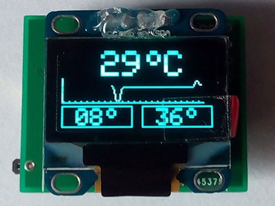
Play
If you power the Arduino modules, the OLED Display connected to the Receiver Arduino will start to show the Temperature+Humidity from the First Sender, and the Temperature+Humidity received from the Second Sender Arduino.
Congratulations! You have completed your project with Visuino. Also attached are the Visuino project files for Sender and Receiver, which I created for this tutorial. You can download it and open it in Visuino: https://www.visuino.eu
Downloads
Download full project file: NRF24L011-Receiver-DHT-Packet.visuino
Download full project file: NRF24L011-Sender-DHT-Packe2t.visuino
Download full project file: NRF24L011-Sender-DHT-Packet.visuino