Auto Cooling Fan Using Servo and DHT11 Temperature and Humidity Sensor W
2026-04-28 | By Ron Cutts
License: GNU Lesser General Public License Humidity Motors Servo Temperature Arduino ESP32
In this tutorial, we will learn how to start & rotate a fan when the temperature rises above a certain level.
What You Will Need
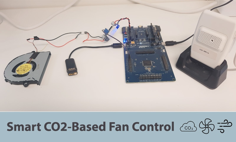
Arduino UNO (or any other board)
Fan module L9110
Visuino program: Download Visuino


The Circuit
Connect the Servo motor "Orange" (signal) pin to Arduino Digital pin[2]
Connect the servo motor. "Red" pin to Arduino positive pin[5V]
Connect the servo motor "Brown" pin to the Arduino negative pin[GND]
Connect the fan module pin [VCC] to the Arduino pin [5V]
Connect the fan module pin [GND] to the Arduino pin [GND]
Connect the fan module pin [INA] to Arduino digital pin [5]
Connect OLED Display pin[VCC] to Arduino pin[5V]
Connect OLED Display pin[GND] to Arduino pin[GND]
Connect OLED Display pin[SDA] to Arduino pin[SDA]
Connect OLED Display pin[SCL] to Arduino pin[SCL]
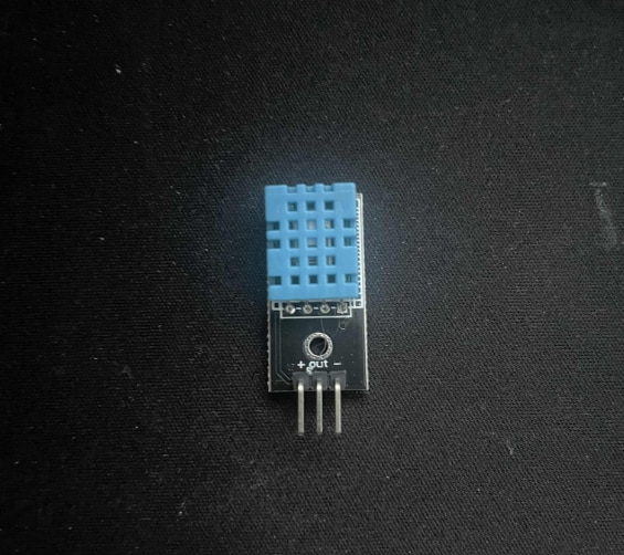
Connect DHT11 positive pin + (VCC) to Arduino pin +5V
Connect DHT11 negative pin - (GND) to Arduino pin GND
Connect DHT11 pin (Out) to Arduino digital pin (4)

Start Visuino, and Select the Arduino UNO Board Type
The Visuino: https://www.visuino.eu needs to be installed. Start Visuino as shown in the first picture. Click on the "Tools" button on the Arduino component (Picture 1) in Visuino. When the dialog appears, select "Arduino UNO" as shown in Picture 2


In Visuino, add components.
Add "Sine Analog Generator" component
Add "Servo" component
Add "DHT" component
Add "Analog Value" component
Add 2X "Compare Analog Value" component
Add "OLED" component


In Visuino Set Components
Select "SineAnalogGenerator1" and in the properties window, set Amplitude to 0.30 and Frequency to 0.1; set Enabled to False; click on the Pin icon; and select Boolean sink pin
Select "CompareValue1" and in the properties window set Value to 24 (temperature that will start the fan) and Compare Type to ctBiggerOrEqual
Select "CompareValue2" and in the properties window, set Value to 24 (temperature level that will stop the fan) and Compare Type to ctSmaller
Double-click on the "AnalogValue1" and in the Elements window, drag "Set Value" to the left
In the properties window, set Value to 0.5
In the Elements window, drag another "Set Value" to the left
In the properties window, set Value to 1
Double-click on the "DisplayOLED1"
In the Elements window:
Drag "Draw Text" to the left and in the properties window, set Text to "TEMP"
Drag "Text Field" to the left and in the properties window, set Size to 2 and Y to 9
Drag "Draw Text" to the left and in the properties window, set Text to "HUMIDITY" and Y to 26
Drag "Text Field" to the left and in the properties window set Size to 2 and Y to 36
Drag "Draw Text" to the left and in the properties window, set Text to "FAN ACTIVE" and Y to 54, and set Enabled to false, click on the pin icon, and set BooleanSinkPin
Close the Elements window


In Visuino Connect Components
Connect SineAnalogGenerator1 pin [Out] to Servo1 pin [In]
Connect Servo1 pin [Out] to Arduino digital pin [2]
Connect "HumidityThermometer1" pin[Sensor] to Arduino digital pin [4]
Connect "HumidityThermometer1" pin[Temperature] to DisplayOLED1>TextField1 pin[In] and CompareValue1 pin[In] and CompareValue2 pin[In]
Connect "HumidityThermometer1" pin[Temperature] to DisplayOLED1>TextField2 pin[In]
Connect "CompareValue1" pin[Out] to DisplayOLED1>DrawText3 pin[Iclock] and pin[Enabled]
Connect "CompareValue1" pin[Out] to AnalogValue1>Set Value1 pin[In] and SineAnalogGenerator1 pin[Enabled]
Connect "CompareValue2" pin[Out] to AnalogValue1>Set Value2 pin[In]
Connect "DisplayOLED1" pin I2C [Out] to Arduino board I2C [In]


Generate, Compile, and Upload the Code
In Visuino, at the bottom, click on the "Build" tab, make sure the correct port is selected, then click on the "Compile/Build and Upload" button.

Play
If you power the Arduino UNO module, the OLED display will start to show the temperature and humidity values, and if the fan is active. Once the temperature rises above 24 degrees, the fan will start to spin.
Congratulations! You have completed your project with Visuino. Also attached is the Visuino project that I created for this. You can download it and open it in Visuino: https://www.visuino.eu