Mfr Part # HP-TPU TRANSPARENT 1KG
HP-TPU TRANSPARENT 1KG
Creality 3D
Since I first tried 3D printing over 8 years ago, things have definitely changed. I’ve noticed significant changes in the 3D printing world in the last couple of years. Along with these massive workflow improvements, I’ve stumbled upon several tips and tricks that I thought would be worth gathering into one article.
In the past couple of years, the 3D printing community has seen our printers move from devices that needed constant tinkering to machines that are getting closer to “upload a file and push print.” The addition of auto-calibrations—such as automatic bed leveling, automatic flow rate calibration, vibration compensation, input shaping, and many other calibrations built into the machine’s automatic calibration sequence—has almost completely eliminated many of the problems users used to fight with on an almost-every-print basis. These calibrations alone have made printing much more appealing to people than the machines of old.
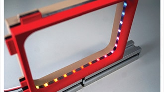
Filaments used with 3D printers have also seen a number of new varieties, as well as changes that make them easier to use. For example, Hyper Speed filaments from Creality enable faster printing profiles because the material is formulated to melt more quickly than traditional filaments, keeping up with printers that are now printing 10 times as fast as printers introduced only a few years ago. A number of 3D printer filament manufacturers have also introduced faster-printing TPU filaments, such as Creality’s HP-TPU, which enable printers to print flexible filaments 3 to 5 times faster than they can with regular TPU filament.
With all of these new filaments, it’s important to consider the tradeoffs of the various varieties. Carbon-fiber-infused filaments can produce stiffer, stronger parts; however, they often come with tradeoffs such as increased brittleness, nozzle wear, and reduced layer adhesion. If you require lightweight parts, such as those used in RC airplanes, there is filament specifically designed for this application, such as Fabru’s Lightweight PLA. The tradeoff for this material is that it requires some tinkering to dial in the temperature and flow to get the desired print weight. This LW-PLA works by foaming caused by raising the nozzle temperature and decreasing the flow rate to make up for the amount of foaming during extrusion.
Ventilation is another area that is often overlooked. While ventilation is recommended for all printing, some filaments are significantly worse than others and may require active air filtration or even external ventilation. There are many articles about ventilation out there, so I will breeze past this without much more than a note.
If you are trying to get pieces to fit together nicely, or even just trying to get two pieces to sit flush when attached together, tolerances can play a big role in your prints. The image below was borrowed from an excellent blog that I happened across a few weeks ago, which I’ve saved as it is a great resource: Design for 3D-Printing - Rahix' Blog

As you can see in the image above, if you design your part to the exact dimension and your printer is out of tolerance (10% shown above may be a bit extreme), it can overshoot what you’re looking for in fitment. If you design in a tolerance—I typically like to use 0.20 mm on most things—your parts will fit much better. Bolts will pass through holes more easily, parts will fit better, and assembly should be smoother. Those small changes can make the difference between a clean fit and a part not fitting at all.
One of the biggest tips I’ve learned over the years of modeling and printing is that just because something looks really good in CAD doesn’t mean it will print well. Here are a few quick tips to help create better CAD designs for 3D printing:
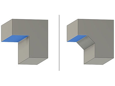
If it’s possible in your design, add chamfers under overhangs. If you can add 45-degree chamfers, you can completely remove the need for supports on those areas. The image below was borrowed from the previously mentioned blog as well.

If your design doesn’t need complex geometry, simplify it as much as you can. Removing unnecessary complexity can make parts much easier to print.
Another option is to make your design modular. While browsing for pictures for a recent workshop I did for a regional FIRST Robotics Competition on this subject, I came across the FRC Modular Limelight Camera Mount on Printables from Ed Yazbec. The neat thing about this design is that it uses the same two mounting brackets for the base and the Limelight camera, but it’s modular in the sense that you can modify the mounting angle by printing the support braces in different orientations. It’s also oriented so the braces are printed flat on the build plate, which helps them withstand a good amount of force (for example, if a collision with the sensor were to happen). It also eliminates the need for support—if the print were built as one solid piece, there would be a number of overhangs and tricky angles that would require lots of extra support.


Crush ribs are small ridges that are added to holes that are meant to intentionally deform, causing a tight fit without a lot of effort. Below is an example of a design with crush ribs. One thing to note if you plan on using crush ribs is that they are a one-time use. Once they are crushed, they will not go back to their original shape.

Another option for press-fitting parts together is to use hexagonal holes instead of round ones. By using a hexagon, you limit the contact points where your round press-fit piece will touch. This can give you a decently tight fit without needing as much force to press everything together.
If you’re looking for something that allows repeatable use, Slant 3D on YouTube showed an example of grip fins. The image below shows an example of the grip fins in a design from their video. Grip fins are designed to use the elasticity of the plastic to deform just a little in order to create a tight fit. This type of design is a great option if you need to reuse the press fit more than once.

While I’m talking about different tricks for holes in 3D printing, I have to mention teardrop-shaped holes. Teardrop-shaped holes help printed holes come out closer to the correct dimension. When you print a circular hole on a vertical axis, the top of the hole tends to droop a bit, which can cause tighter-than-anticipated fitment of connectors. By using a teardrop shape, you give the top of the hole an angled “roof,” which is easier for the printer to handle. On larger holes, the teardrop shape doesn’t even need to come to a point. Once you add extra clearance at the top of the hole, the printer should be able to bridge without too much sagging. In the image below, the 4 mm hole on the right comes to a 90-degree angle at the top. For the 10 mm hole on the left, the roof of the hole is offset 0.4 mm above the edge of the circle so that, if it sags just a bit, it will still fit nicely. Below that image, I have a GIF walking through the layers in a slicer. In the slicer GIF, you’ll notice that I added two other holes for comparison; they are both 4 mm and 10 mm to match the teardrop-shaped ones. As you watch the GIF and get near the top of the holes, you’ll notice that the overhang on both sides gets more and more extreme. This is what causes sagging when holes are printed in a vertical orientation.


I’m not quite sure where I first saw this trick, but there’s a counterbore-hole design that allows them to be printed on the underside of parts without requiring support. The trick works by adding bridging layers before the hole starts printing. In the example below, I drew a sketch based on the edges of the hole itself, then cut the two longer sides down 0.2 mm (or 1 layer height, depending on what layer height you’re using), and then took the two sections on the top and bottom of the circle and cut those down 0.4 mm. This creates two layers of bridging before the hole starts printing.
As I’ve been creating the GIFs and videos for this blog, I learned that some slicers based on OrcaSlicer have a new option that does this entirely in the slicer, without requiring any modifications in CAD. I found that OrcaSlicer, Elegoo Slicer, and Creality Slicer have this enabled already, and I’m sure that if it’s not in others, it will be soon. Below is a screenshot of what the option looks like in the menu. I’ve also included a GIF of each option. In the GIFs, the first is with None selected, the second is with Partially bridged, and the last is with the Sacrificial layer. The hole in the center of the part has the CAD modification above, and the one on the top left is just a standard counterbore hole.


On a lot of the projects I’ve created, I have multiple mounting holes. In the past, I had to print the whole object (or split it in CAD) to verify if everything fit correctly. Over the past couple of years, slicer software has added split tools. I use this a lot when I’m testing fitment of mounting holes or interfacing parts, to make sure they fit correctly before printing the full project. For example, I’ve been working on a Bluetooth speaker that is modeled after a vintage radio. On the base of the speaker, I have the mounting holes for the Bluetooth receiver board. The only problem is that the speaker prints face down, so in the past, I would have had to print the full piece just to test those mounting holes. With the new split tool, I was able to break the print down to only the piece I wanted to verify and cut print time from almost 6 hours to just under 30 minutes. I’ve included some screenshots below for reference.


Another tip that I’ve stumbled across over time is that a great balance of speed and strength is to set your layer height to about half of your nozzle width. For example, if you are using a 0.4 mm nozzle, a solid starting point is a 0.2 mm layer height; or if you are using a 0.6 mm nozzle, try a 0.3 mm layer height. While you can go with a taller layer height, the tradeoff is usually a rougher finish. If you go the other way and use a thinner layer height, print time increases quite quickly. For example, if you drop from a 0.2 mm layer height to a 0.1 mm layer height, your print time will roughly double. The result can look nicer—especially if you have fine details—but you’ll have to wait longer for it to finish.
The next thing that usually comes up after layer height is infill. One of the considerations that I use for infill choice is the direction of the force on the part. For example, if there is going to be an outside force on the part, I typically like to use a triangular infill or even gyroid. I’ve gotten away from using grid infill recently because it seems that if there are issues that happen internally on parts while printing, it’s because of where the infill crosses over itself. Gyroid is a pretty neat option for infill that I tend to use quite a bit.
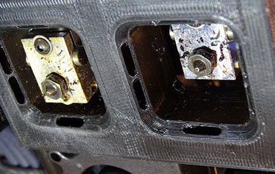
Another slicer trick that can help with strength is modifiers. If you want extra strength around (for example) a bolt hole, you can use a modifier to increase the infill percentage just around that area, so the mounting point is stronger than the rest of the print, and extra filament isn’t wasted where it isn’t needed. The first image below shows the yellow modifier added around the bolt hole on the block, and the image below that shows the modified infill type and density in the part. This can also be used to add additional walls to an area so that there is more strength as well.


With how fast printers have been evolving, slicer software has been moving at an equally rapid pace. As mentioned previously, auto-calibration has become much easier than it has ever been in the past. If you are still having problems with some of your trickier filaments, many slicers have built-in calibration tests that can help you fine-tune your print profile and dramatically increase your chances of a successful print. Orca Slicer and Creality Slicer, for example, have a series of calibration tests built into the slicer to help you achieve the best quality prints. They even include a link to a tutorial that explains which order the tests should be completed in, what each test is doing, and how to find the best results.

In a lot of the various groups and forums that I participate in, it seems that a good majority of the issues I see people having are bed-adhesion related. One thing that I’ve found works really well is to use a 50/50 mix of isopropyl alcohol and water in a spray bottle. Spray it on the bed and wipe it down thoroughly with a clean, lint-free cloth. With some of the newer textured PEI beds, manufacturers recommend using a good grease-removing dish soap.
Three of the most common print failures that appear over and over again are warping, stringing, and layer shift. With many of the most common filaments used today—PLA and PETG—warping isn’t quite as much of an issue as it used to be with filaments such as ABS. Even though it isn’t as prevalent as it once was, new features have been added to slicers to help mitigate warping. Brims have long been a useful tool for helping with adhesion. More recently, there has been a setting called Mouse Ears in the brim settings. This adds a small circular brim to the sharp corners of your print to help with adhesion. This is especially useful if you have a corner that likes to lift. Here is what a mouse-ear brim looks like.

While this blog could keep going on and on with tips I’ve uncovered, here is one final one that I thought I would share. Designing material-saving holes can seem like a good idea; however, always double-check in your slicer to make sure it’s actually saving you material. Below is an example from the blog previously mentioned that shows what I mean. The designer of the part added holes in order to save material. When the part was actually run through the slicer, it was discovered that it took extra filament and time to print.

The flip side to the above part is that the part with holes would have added strength because the holes would add internal walls to the part. The part on the right without the holes would only have infill.
Hopefully, this has been a useful blog for you. That’s my current shortlist, but it’s definitely not the finish line. The best 3D printing workflows I’ve seen are built from lots of small lessons shared over time. If you’ve got a favorite setting, design trick, or “this saved my print” habit, post it in the comments below—let’s turn this into a living list everyone can build on.